Product Information
Critical Assets include switchgear, generator circuit breakers, rectifier stacks, transformers, load tap changers, transformer bushings, RMU’s, LV Distribution Panels, Bus Ducts (ISO, poly-phase & uni-phase), capacitor reactor banks, cable boxes, cable terminations, Motor Controllers, dry type transformers, etc.
The vast majority of critical assets in the field today are greater than 25 years old.
— Less than 5% of installed critical assets have continuous monitoring integrated.
— Temperature is the leading indicator of critical asset failure.
— Critical asset failure is one of the leading causes of power outages.
— The average cost of critical asset failure is greater than $500K per event.
— The ROI for implementing continuous switchgear monitoring is less than 12 months.
— Critical asset failure often involves injury to humans, and is known to cause deaths.
Today, more than ever before, the customer demand on electric power transmission and distribution infrastructure is rising. This fact, coupled with aging equipment, leads to more electric power switchgear being stressed up to and beyond its original rated capacity. Increasing maintenance schedules dictated by the need to save costs do not help this situation. The operating temperature of switchgear has been found to have a very high correlation to the operational life of the asset: when switchgear are operated at very high temperatures, the likelihood of failure increases dramatically. Consequently, monitoring the temperature of likely failure points within electric power switchgear provides invaluable data on the health of that piece of equipment: early detection of incipient problems leads to rapid identification of problems and can provide significantly better maintenance scheduling that result in little or no down-time associated with switchgear failure.
“Corona is a serious issue in metal clad switchgear because of its highly destructive nature. It is the cause of most flashovers in medium-voltage metal clad electrical equipment. The fundamental cause of this symptom is an electrical breakdown of air brought on by electrical stress and poor air quality within the switchgear. If not rectified a flashover is imminent, possibly causing enormous damage and injury to personnel.” (HiVec Canada, Inc. abstract of a whitepaper on Avoiding Flashover in Medium-Voltage Switchgear;
Clearly, if there is a need to understand the health of switchgear by monitoring its temperature, the method of measuring temperature MUST NOT contribute to any failure mechanisms, especially flashover. For medium-voltage and high-voltage equipment, anything that touches medium-voltage or high-voltage conductors must never violate the air-dielectric separation design requirements for the operating voltage. It is almost impossible to guarantee the dielectric separation needed for such equipment with wired temperature monitoring solutions. Both the safety and liability concerns of wired solutions prohibit their use in these applications.
Wireless solutions for temperature monitoring of medium-voltage and high-voltage switchgear are a necessity.
Passive wireless radio-based temperature monitoring systems are ideal for medium-voltage and high-voltage electric power switchgear. Once installed (typically during normal service periods), passive wireless temperature sensors have all the advantages of battery-powered sensors but have service-free lifetimes exceeding 20 years. Properly installed passive radio-based wireless sensor systems are truly set-and-forget monitoring instruments for medium-voltage and high-voltage switchgear.
There have been numerous cases of the load through medium-voltage or high-voltage switchgear changing very rapidly, leading to catastrophic results. This can be a result of new loads imposed on a circuit that are unknown to the switchgear operator, or can be a result of events such as animals unexpectedly altering the air-dielectric behavior in switchgear, with disastrous results (both for the animal and for the switchgear).
Continuous monitoring of switchgear temperature can identify rapidly changing conditions on the switchgear and can initiate predictive and preventative measures early enough to prevent loss of equipment, and, in many cases, interruption of service. Alerts, alarms and trend-tracking based on temperature data are critical when the environment of the switchgear changes quickly.
Typically, a medium-voltage or high-voltage switch has at least four areas of concern to operational staff: the input bus bars in the cabinet, the input connections to the switch or breaker itself, the output connections from the switch or breaker and the output cable connections. Each of these areas has three phases of power, so there are 12 locations that ought to be monitored to assess the health of the equipment. Clearly, the absolute minimum critical locations are the inputs and outputs of the switch or breaker, so at a minimum, the temperature of 6 locations is of the highest importance.
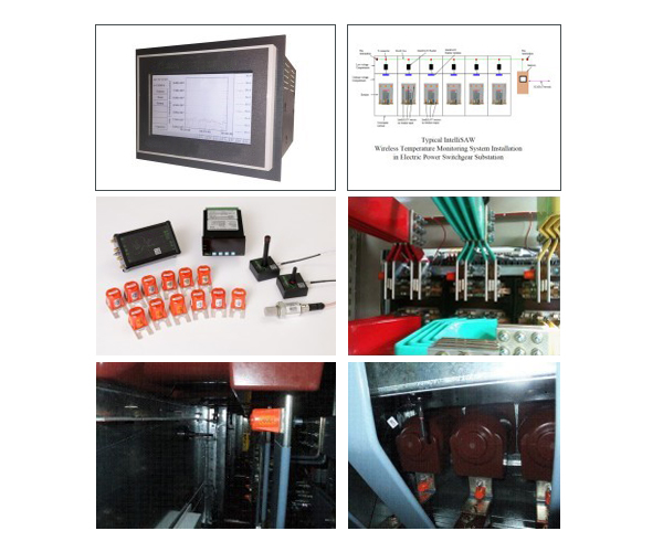
The IntelliSAW wireless temperature monitoring system consists of three main components: the passive wireless temperature sensors (not requiring any power supply), the reader and the network connecting all of the readers together with asset management infrastructure.
The sensors along with the reader antennas are deployed wherever temperatures need to be monitored, usually in the elevated-voltage compartment. The readers are installed in the low-voltage compartment, generally with other monitoring and communication equipment. Each of the readers is connected to each other and the asset management system via one or more networks, possibly using intermediate gateway devices. The gateways provide aggregation and data-management functions between low-intelligence readers and high-functionality asset management systems. Additionally, the gateways can provide local diagnostic and test functions as well as diverse data archival functions.
IntelliSAW wireless temperature monitoring systems provide data to the asset management network using industry-standard Modbus protocols over a standard RS485 serial bus. Each reader on the RS485 bus is configured to have a unique Modbus address during commissioning. During commissioning, each reader is configured to report the data from the sensors associated with it. The temperature data for each sensor (from an addressed reader) is provided in Modbus holding registers that can be read with standard Modbus commands. In addition to temperature, the holding registers also provide the received signal level, the measurement standard deviation and an indication of data validity for each sensor of an addressed reader.
IntelliSAW wireless temperature monitoring systems utilize passive wireless temperature sensors that need no external power to operate. All necessary power is provided by the RF interrogation signal.

